Nissan Altima (L32) 2007-2012 Service Manual: Engine control system QR25DE except for california
Basic inspection
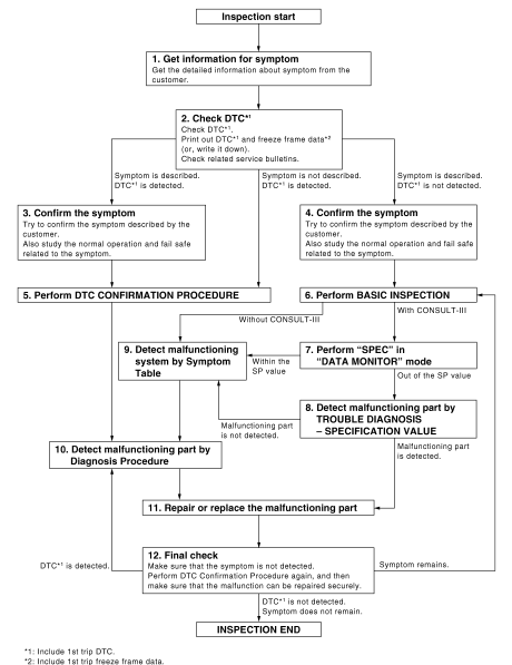
DIAGNOSIS AND REPAIR WORK FLOW
Work Flow
OVERALL SEQUENCE

DETAILED FLOW
1.GET INFORMATION FOR SYMPTOM
Get the detailed information from the customer about the symptom (the condition and the environment when the incident/malfunction occurred) using the “Diagnostic Work Sheet”. (Refer to EC-558, "Diagnostic Work Sheet".) >> GO TO 2.
2.CHECK DTC
1. Check DTC.
2. Perform the following procedure if DTC is displayed.
- Record DTC and freeze frame data. (Print them out with CONSULT-III or GST.) - Erase DTC. (Refer to EC-641, "Diagnosis Description".) - Study the relationship between the cause detected by DTC and the symptom described by the customer.
(Symptom Table is useful. Refer to EC-1027, "Symptom Table".) 3. Check related service bulletins for information.
Is any symptom described and is any DTC detected? Symptom is described, DTC is detected>>GO TO 3.
Symptom is described, DTC is not detected>>GO TO 4.
Symptom is not described, DTC is detected>>GO TO 5.
3.CONFIRM THE SYMPTOM
Try to confirm the symptom described by the customer (except MIL ON).
Also study the normal operation and fail safe related to the symptom. Refer to EC-1031, "Description" and EC- 1012, "Fail Safe".
Diagnosis Work Sheet is useful to verify the incident.
Verify relation between the symptom and the condition when the symptom is detected.
>> GO TO 5.
4.CONFIRM THE SYMPTOM
Try to confirm the symptom described by the customer.
Also study the normal operation and fail safe related to the symptom. Refer to EC-1031, "Description" and EC- 1012, "Fail Safe".
Diagnosis Work Sheet is useful to verify the incident.
Verify relation between the symptom and the condition when the symptom is detected.
>> GO TO 6.
5.PERFORM DTC CONFIRMATION PROCEDURE
Perform DTC CONFIRMATION PROCEDURE for the displayed DTC, and then make sure that DTC is detected again.
If two or more DTCs are detected, refer to EC-1014, "DTC Inspection Priority Chart" and determine trouble diagnosis order.
NOTE: • Freeze frame data is useful if the DTC is not detected.
• Perform Component Function Check if DTC CONFIRMATION PROCEDURE is not included on Service Manual. This simplified check procedure is an effective alternative though DTC cannot be detected during this check.
If the result of Component Function Check is NG, it is the same as the detection of DTC by DTC CONFIRMATION PROCEDURE.
Is DTC detected? YES >> GO TO 10.
NO >> Check according to GI-42, "Intermittent Incident".
6.PERFORM BASIC INSPECTION
Perform EC-560, "BASIC INSPECTION : Special Repair Requirement".
Do you have CONSULT-III?
YES >> GO TO 7.
NO >> GO TO 9.
7.PERFORM SPEC IN DATA MONITOR MODE

Make sure that “MAS A/F SE-B1”, “B/FUEL SCHDL” and “A/F ALPHA-B1” are within the SP value using CONSULT- III in “SPEC” of “DATA MONITOR” mode. Refer to EC-665, "Component Function Check".
Is the measurement value within the SP value? YES >> GO TO 9.
NO >> GO TO 8.
8.DETECT MALFUNCTIONING PART BY TROUBLE DIAGNOSIS - SPECIFICATION VALUE
Detect malfunctioning part according to EC-666, "Diagnosis Procedure".
Is malfunctioning part detected? YES >> GO TO 11.
NO >> GO TO 9.
9.DETECT MALFUNCTIONING SYSTEM BY SYMPTOM TABLE
Detect malfunctioning system according to EC-1027, "Symptom Table" based on the confirmed symptom in step 4, and determine the trouble diagnosis order based on possible causes and symptom.
>> GO TO 10.
10.DETECT MALFUNCTIONING PART BY DIAGNOSIS PROCEDURE
Inspect according to Diagnosis Procedure of the system.
NOTE: The Diagnosis Procedure in EC section described based on open circuit inspection. A short circuit inspection is also required for the circuit check in the Diagnosis Procedure. For details, refer to Circuit Inspection in GI- 45, "Circuit Inspection".
Is malfunctioning part detected? YES >> GO TO 11.
NO >> Monitor input data from related sensors or check the voltage of related ECM terminals using CONSULT- III. Refer to EC-978, "Reference Value".
11.REPAIR OR REPLACE THE MALFUNCTIONING PART
1. Repair or replace the malfunctioning part.
2. Reconnect parts or connectors disconnected during Diagnosis Procedure again after repair and replacement.
3. Check DTC. If DTC is displayed, erase it. Refer to EC-641, "Diagnosis Description".
>> GO TO 12.
12.FINAL CHECK
When DTC was detected in step 2, perform DTC CONFIRMATION PROCEDURE or Component Function Check again, and then make sure that the malfunction have been repaired securely.
When symptom was described from the customer, refer to confirmed symptom in step 3 or 4, and make sure that the symptom is not detected.
Is DTC detected and does symptom remain? YES-1 >> DTC is detected: GO TO 10.
YES-2 >> Symptom remains: GO TO 6.
NO >> Before returning the vehicle to the customer, make sure to erase unnecessary DTC in ECM and TCM (Transmission Control Module). (Refer to EC-641, "Diagnosis Description".) If the completion of SRT is needed, drive vehicle under the specific DRIVING PATTERN in EC-1018, "How to Set SRT Code".
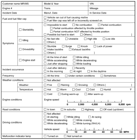
Diagnostic Work Sheet
DESCRIPTION
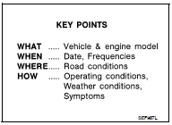
There are many operating conditions that lead to the malfunction of engine components. A good grasp of such conditions can make troubleshooting faster and more accurate.
In general, each customer feels differently about an incident. It is important to fully understand the symptoms or conditions for a customer complaint.
Utilize a diagnostic worksheet like the one on the WORKSHEET SAMPLE in order to organize all the information for troubleshooting.
Some conditions may cause the MIL to come on steady or blink and DTC to be detected. Examples: • Vehicle ran out of fuel, which caused the engine to misfire.
• Fuel filler cap was left off or incorrectly screwed on, allowing fuel to evaporate into the atmosphere.

WORKSHEET SAMPLE

- Inspection and adjustment
- Basic inspection
- Additional service when replacing control unit
- Idle speed
- Ignition timing
- Vin registration
- Accelerator pedal released position learning
- Throttle valve closed position learning
- Idle air volume learning
- Mixture ratio self-learning value clear
- Function diagnosis
- Engine control system
- Multiport fuel injection system
- Electric ignition system
- Air conditioning cut control
- Automatic speed control device (ASCD)
- Can communication
- Cooling fan control
- Evaporative emission system
- Intake valve timing control
- On board diagnostic (OBD) System
- Component diagnosis
- Trouble diagnosis - specification value
- Power supply and ground circuit
- U0101 Can comm circuit
- U0140 Can comm circuit
- U1001 Can comm circuit
- P0011 IVT Control
- P0031, P0032 A/F Sensor 1 heater
- P0037, P0038 HO2S2 Heater
- P0075 ivt control solenoid valve
- P0101 maf sensor
- P0102, p0103 maf sensor
- P0112, p0113 iat sensor
- P0116 ect sensor
- P0117, p0118 ect sensor
- P0122, P0123 TP Sensor
- P0125 ECT Sensor
- P0127 IAT Sensor
- P0128 Thermostat function
- P0130 A/F Sensor 1
- P0131 A/F Sensor 1
- P0132 A/F Sensor 1
- P0133 A/F Sensor 1
- P0137 HO2S2
- P0138 HO2S2
- P0139 HO2S2
- P0171 fuel injection system function
- P0172 fuel injection system function
- P0181 FTT Sensor
- P0182, P0183 FTT Sensor
- P0222, P0223 TP Sensor
- P0300, P0301, P0302, P0303, P0304 Misfire
- P0327, P0328 KS
- P0335 CKP Sensor (POS)
- P0340 CMP Sensor (phase)
- P0420 three way catalyst function
- P0441 evap control system
- P0442 evap control system
- P0443 evap canister purge volume control solenoid valve
- P0444, p0445 evap canister purge volume control solenoid valve
- P0447 evap canister vent control valve
- P0448 evap canister vent control valve
- P0451 evap control system pressure sensor
- P0452 evap control system pressure sensor
- P0453 evap control system pressure sensor
- P0455 evap control system
- P0456 evap control system
- P0460 fuel level sensor
- P0461 fuel level sensor
- P0462, p0463 fuel level sensor
- P0500 VSS
- P0506 ISC System
- P0507 ISC System
- P0550 PSP Sensor
- P0603 ECM Power supply
- P0605 ECM
- P0607 ECM
- P0643 sensor power supply
- P0850 PNP Switch
- P1148 closed loop control
- P1217 engine over temperature
- P1225 TP Sensor
- P1226 TP Sensor
- P1421 cold start control
- P1550 battery current sensor
- P1551, P1552 Battery current sensor
- P1553 battery current sensor
- P1554 battery current sensor
- P1564 ASCD Steering switch
- P1572 ASCD Brake switch
- P1574 ASCD Vehicle speed sensor
- P1715 input speed sensor (primary speed sensor)
- P1805 brake switch
- P2100, p2103 throttle control motor relay
- P2101 electric throttle control function
- P2118 throttle control motor
- P2119 electric throttle control actuator
- P2122, P2123 APP Sensor
- P2127, P2128 APP Sensor
- P2135 TP Sensor
- P2138 APP Sensor
- P2A00 A/F Sensor 1
- ASCD Brake switch
- ASCD Indicator
- Cooling fan
- Electrical load signal
- Fuel injector
- Fuel pump
- Ignition signal
- Malfunction indicator lamp
- On board refueling vapor recovery (ORVR)
- Positive crankcase ventilation
- Refrigerant pressure sensor
- Ecu diagnosis
- Symptom diagnosis
- Precaution
- Preparation
- On-vehicle maintenance
- On-vehicle repair
- Service data and specifications (SDS)

 Service data and specifications
(SDS)
 Inspection and adjustment